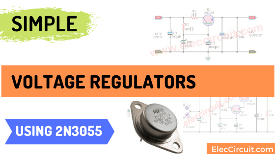

- #2n3055 transistor pin configuration drivers
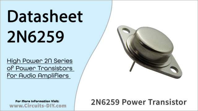
- #2n3055 transistor pin configuration full
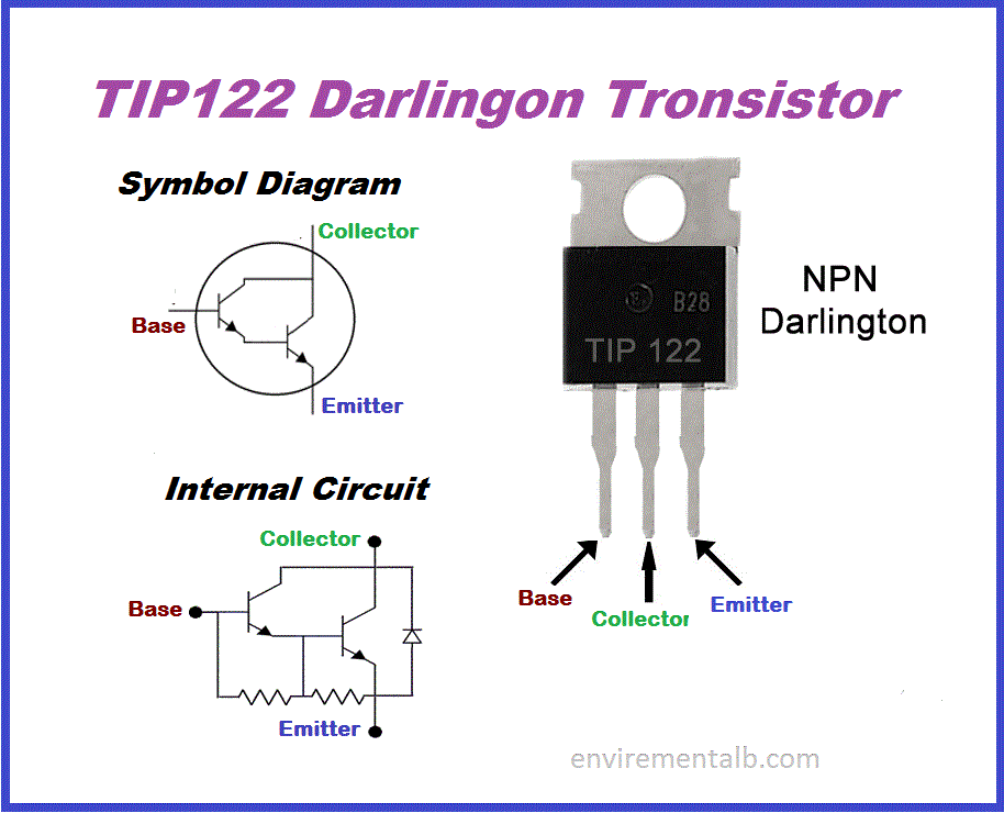
- #2n3055 transistor pin configuration series
77W at 10A which will mean a rise in temperature of about 48C degrees C over ambient. With an R DS ot 0.077ohms will give about. The dissipation would be the IRL540 should work but it will get a little hot. Hi dc42, no offense intended here, but I think you made a little error on the math. Look for a mosfet with much lower Rds(on), such as IRLU8726PBF (0.008 ohms max).

IRL540 is not a good mosfet to use for switching 10A, its Rds(on) is 0.077 ohms max so it will dissipate around 7.7W when carrying 10A.

With Faraday's law, the delta-T is in the denominator, so the less time it takes for the magnetic field to collapse, the higher the voltage is. The energy is the same, the "delta-T" is much smaller. The SAME energy (less losses) that you put into the rubber band stretching it is returned when you release it, but because it's faster, the "snap" stings your skin. When you let go of the top, the rubber band will snap DOWN (negative) very fast. Say you hold the bottom of the rubber band and stretch the top end higher and higher (more and more "positive"). So, normally the diode does nothing (reverse biased), But if an inductive kickback occurs, the diode is forward biased and "snubs" the spike. the PWM goes to the "off" cycle), the magnetic field collapses and can generate hundreds to thousands of volts in the OPPOSITE direction. So, if you put +12 volts into the motor, when you de-energize it (i.e. Faraday's law basically says that the faster a magnetic field changes, the higher the voltage induced in the wire. When the current is removed, the magnetic field collapses almost instantly. When the motor is energized, a magnetic field forms on the armature. What the diode does is protect the 2N3055 from inductive kickback. The resistors you highlighted are not necessary. What should be the values?Īlso: what is the functionality of the 1N4007 diode next to the motor? And do I need to put another diode from the collector to the emitter of the 3055? I don't know if I need the two green resistors (with question marks), I didn't use them in the test but I saw that some people use them. The circuit works but I'm not sure that is perfectly ok.

In the picture you can see that I'm using a 2n2222 that controls a TIP3055 (or a 2N3055).
#2n3055 transistor pin configuration full
It does not store any personal data.I need to control the speed of a dc motor (0.5 A no load, to 10 A full load). The cookie is set by the GDPR Cookie Consent plugin and is used to store whether or not user has consented to the use of cookies. The cookie is used to store the user consent for the cookies in the category "Performance". This cookie is set by GDPR Cookie Consent plugin. The cookie is used to store the user consent for the cookies in the category "Other. The cookies is used to store the user consent for the cookies in the category "Necessary". The cookie is set by GDPR cookie consent to record the user consent for the cookies in the category "Functional". The cookie is used to store the user consent for the cookies in the category "Analytics". These cookies ensure basic functionalities and security features of the website, anonymously. Necessary cookies are absolutely essential for the website to function properly.
#2n3055 transistor pin configuration series
The a power supply of 80V, it becomes necessary to put a series capacitor in between the output stage and the speaker in order to block the DC supply from entering the speaker and allowing only the amplified 100 watt music power. The 2N3055 power stage at the output should be mounted on large heat sinks to ensure that this crucial stage is able to dissipate adequately and function with optimal efficiency.
#2n3055 transistor pin configuration drivers
The input stage is created by configuring a couple of current drivers transistor stages responsible for triggering the pairs of power BJTs positioned at the output stage. Simply by incorporating just four transistors in the quasi-complementary configuration this 2N3055 simple power amplifier circuit can deliver a good 100 watts of power over an attached 4 ohms loud speaker, and the entire design can be built at a really low cost (to be precise it would cost you only 1/2$ per transistor).Īs exhibited in the above diagram you won't find no costly or obsolete hard to find components in this amplifier circuit, except the power supply transformer and possibly the 4 ohm loud speaker.


 0 kommentar(er)
